DESIGN YOUR OWN WIRED ROBOT FOR FESTS
1. Introduction-
This is a primer project which covers following concepts-
- Power Supply.-Rectifier
- DPDT switch operation.
- D.C. Motor.
- Basic motion of Robot
2. Tools & Components –
There are following tools are required for this project-
- Soldering iron - for the strong joints
- Hack saw/ blade - to cut remote
- Screw drivers - get your tool kit- it comes easy
- Multimeter - to check current
- Cutter - to uncover the plastic of wire
- Small Hammer - used for external motors
There are following components are required for this project-
- Battery (6 volt , 4.5 Ah) - 1 nos. (for testing purpose only)
- DPDT Switch- 2nos.
- Ribbon wire strip- 3 meters+
- D.C. motor- 4 nos (used internal gayer motor)
- Chassis(having holes for motor) - 1
- Remote box 1
- Metal strip 12
- Wheels 2 nos.
- Solder 1
- Soldering wire - as per your required
3. Procedure for your ROBO CAR by apnasem-
- PAPER PLANS:
Before you start making your first robot car to have a engineer like feeling in you. You need a paper plan. Measure length of the DC motor , diameter of shaft of the motor, inner hole diameter of the motor. Draw a rough sketch of the base you need to cut keeping in mind the placement of motors and wheels.
Holes to fit caster wheel
Holes for wiring

TOP VIEW
Mechanical Assembly –
Fit the caster wheel at position show in above diagram with 1.5-2 inches (approx.) screw. Fit the dc motor into the holes of chassis and couple the wheel by using screw or rubber tube.


Bolt is to fit outside of chassis
Coupling motors and wheels
- Remote Designing-
Before going to remote we must learn basic movement of robot which is shown in following table.
Movements | Motor1 (left) | Motor2(right) |
For moving forward | Clockwise | Clockwise |
For moving backward | Anticlockwise | Anticlockwise |
For turning left | Off | Clockwise |
For turning right | Clockwise | Off |
To make anti-clockwise motion of motor, the polarity of supply must be inverted of polarity of supply in clockwise motion. For "Polarity Reversal" DPDT(Double Pole Double Throw) switches are generally used. This can be done by using following circuit. Some DPDT Switch has 8 pins in it then 2 pins b/w them will be consider as dead
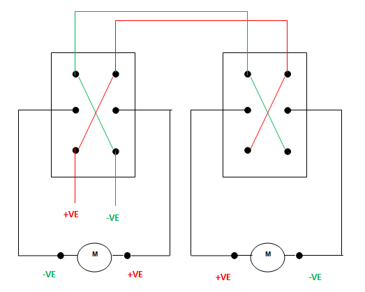
DPDT Switch Connections for REMOTE
The wire should solder on metal strip or PCB or any perforated board , do not solder on switches directly (as shown in fig 3). This precaution helps us if there is wrong connection occurs in circuit. So we can change the circuit by changing metal strip position (fig 4). The procedure is shown in figure below-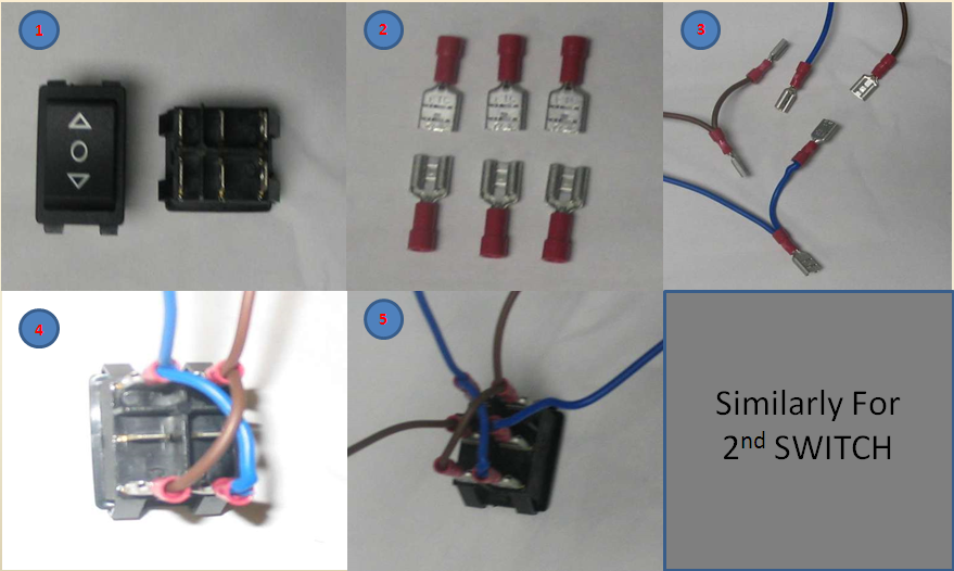
DPDT Connections
4. Motor connections- There will be 4 output wires from remote which is to solder on motors by ribbon wire strip or simple two curly wires using ribbon wire strip will rise possiblity of breaking wire between the length.And it become very difficult to get where the defect arises. Switch1's output should connect motor1 and switch 2's on motor2. This means DPDT switch1 controls motors on left and DPDT switch 2 controls motor on right. Before connecting motors by soldering, the polarity of motor should be check buy giving direct supply from battery.
CAUTION:- Checking the circuit regularly will ease your work. If you don't check the circuit regularly before solderring or after then you may arise to many situations like
1) Forward movement of DPDT Switch 1 and 2 will resut in opposite motion of tyres.
2) Your tyres allignment may disturb.
5. Power Supply-
The rechargeable battery of rating 12 Volt and 3 ampere rating or 24 Volt and 5 ampere should connected with remote switch (as shown in fig).
You can make a transformer by using a rectifier circuit.
FOR THIS MATERIAL REQUIRED ARE:-
1) Transformer( 12volt or 24 volt) which will give you 1,3 or 5 Ampere current.
2) 4 diodes
3) 1 Capacitor
4) Solder

4. Speed calculation of robot-
Speed of robot can be calculate by following formula -
V = 2*pi*r * rpm
V = 2r * pi * rpm OR V = 2 * r * pi * rpm
The RPM of motor will perfect match with its specification if only is power rating of motor is provide by power supply.
Use high torque motor to get through all hurdles.
Learn to drive your robo both fast and slow.
No comments:
Post a Comment
Note: Only a member of this blog may post a comment.